Content
An air brake system is a friction-based braking mechanism that uses compressed air as its power transmission medium. Unlike passenger cars that depend on hydraulic fluid, heavy commercial vehicles — including trucks, buses, and multi-trailer combinations — use compressed air because it is virtually inexhaustible and poses a lower risk of operational failure in case of minor line breaches. In a hydraulic system, a single leak can render the brakes completely useless. An air brake system, by contrast, can often maintain partial functionality through redundant circuits, allowing the vehicle to stop safely even with a compromised circuit.
The technology traces its roots to George Westinghouse, who patented a safer air brake design for railways in 1872. After proving its reliability on trains, the concept was adapted for heavy road vehicles in the early 20th century. Today, a typical truck air brake system operates at a working pressure of approximately 100–120 psi (690–830 kPa), with a compressor charging the reservoirs to a cut-out range of 120–145 psi. The stored energy not only stops the vehicle but often supplies auxiliary pneumatic systems for gear shifting, clutch assistance, and suspension control.
The functional path from a driver’s foot to the wheel end is a sequential chain of energy conversion. Each stage relies on a specific component performing its task within defined pressure thresholds. A failure to generate, store, or transmit air pressure correctly will compromise the entire braking sequence.
The standard operating sequence follows these five stages:
Understanding this flow highlights why a weakness in any single component — a leaking air dryer, a slow relay valve, or an over-stroked brake chamber — directly translates into longer stopping distances.
While auxiliary valves refine the system’s behavior, five core component groups form the backbone of every heavy-duty air brake installation. Recognizing their individual functions and failure patterns is the foundation of systematic troubleshooting.
The compressor is typically gear-driven from the engine and must generate volume faster than the system can consume it. The governor acts as the compressor’s control switch, sensing reservoir pressure and sending an unloader signal when the upper threshold is met. A compressor that cycles continuously without unloading often points to a governor failure or a severe system leak. Equally critical is the quality of the compressed air: excessive oil carryover from a worn compressor can contaminate downstream rubber diaphragms and valve seals, while high air temperature accelerates the deterioration of O-rings.
Reservoirs serve a dual purpose: storing energy for repeated stops and acting as a primary cooling and condensation chamber where water vapor drops out of the hot, compressed air. Without an effective air dryer to filter residual moisture and contaminants, the system suffers from internal corrosion, frozen lines in cold weather, and premature failure of valve pistons and brake chamber diaphragms. A shop-standard maintenance protocol is to manually drain the reservoir petcocks daily, even when an automatic desiccant-type air dryer with replaceable filter elements is fitted to protect valve and chamber life. Inspecting the purge cycle and replacing the desiccant cartridge at the manufacturer-specified interval is mandatory for cold-climate operation.
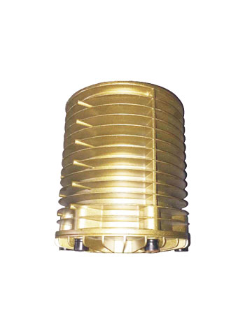 Truck Air Dryers Manufacturers, Trailer Air Dryers FactoryAs a China truck air dryers Manufacturers and Trailer air dryers Factory, Zhejiang VOB Technology Co., Ltd supply kinds of wholesale truc...View Product →
The foot valve is a graduated-control valve that provides a progressive output pressure proportional to pedal force. Internal spool or poppet seals meter supply air to the delivery ports. A common service issue is a sticking or binding pedal linkage, which causes hesitation in application. Internal seal wear results in a constant hiss of air from the exhaust port when the pedal is in the released position, indicating a trip-level air leak that prevents full system charging.
The brake chamber is where pneumatic energy becomes mechanical work. In a standard service chamber, pressure entering the service port pushes a diaphragm against a pushrod plate. In a spring brake chamber, a second compartment houses a heavy power spring that applies the brakes mechanically for parking or emergency stops when system pressure falls below a safe threshold (typically around 60 psi). Common stroke specifications include T16, T20, T24, and T30 types, with mounting configurations such as 24DP, 30DD, and 24DD determining compatibility with specific axle brackets.
The slack adjuster links the chamber pushrod to the brake camshaft. Its job is to multiply torque and compensate for brake lining wear. Manual adjusters require a technician to periodically correct the clearance gap. Automatic adjusters sense the excess stroke and ratchet the adjustment internally to maintain a consistent lining-to-drum clearance. A pushrod stroke exceeding the manufacturer’s limit — often identified during a routine walk-around inspection — indicates an adjuster that has stopped compensating, regardless of being manual or automatic. For fleets aiming to standardize maintenance intervals, automatic slack adjusters configured for self-setting gap control reduce the risk of missed manual adjustments, though they still require lubrication and functional verification at every service interval.
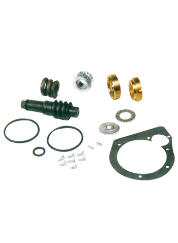 Auto Slack Adjuster Manufacturers, China Auto Slack Adjuster CompanyAs a China Auto Slack Adjuster Manufacturers and Auto Slack Adjuster factory, Zhejiang VOB Technology Co., Ltd. supply wholesale Auto Sla...View Product →
Matching the correct braking components to the vehicle axle is a procurement essential, and reviewing available brake chamber configurations by stroke and mounting type helps confirm cross-compatibility with the existing camshaft and bracket layout.
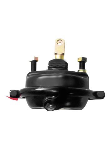 China FAQP Disc Spring Brake Chambers Manufacturers, FactoryAs a China truck spring brake chambers manufacturers and trailer disc brake chambers Factory, Zhejiang VOB Technology Co., Ltd offer FAQP...View Product →
The friction pair converts mechanical clamping force into heat, reducing wheel speed. Drum brakes use a set of shoes faced with high-friction lining that press outward against a rotating drum. Disc brake systems use a chamber or caliper to press pads against a ventilated rotor. Drum brakes dominate in heavy haul because of their high torque output and robust design, though disc brakes offer more consistent performance across a wide temperature range and faster pad changes. Regardless of the type, friction material wear is the primary determinant of brake replacement. A lining worn to within 1/16 inch of the rivet or backing plate demands immediate relining to prevent cam-over events or damage to the drum surface.
On a tractor with a single axle, a simple circuit might suffice. On a multi-trailer combination stretching over 80 feet, the signal delays and pressure differentials between axle groups demand dedicated control valves. These components are what make a pure pneumatic system practical for commercial transport.
A relay valve solves the distance problem. Mounted close to the service brake chambers on a trailer or rear axle, it uses the low-flow pilot signal from the foot valve to open a high-flow path directly from the local reservoir to the chambers. This bypasses the long pipe run from the cab, cutting the application time significantly. A failed relay valve often manifests as a slow wheel response on one axle group while others react normally. Internally, a torn diaphragm or a stuck piston will prevent the valve from either opening or exhausting properly.
Brake drag generates heat and accelerates lining wear. A quick release valve is mounted near the brake chamber service port to vent exhaust air directly at the wheel end the instant the driver lifts the pedal. Without it, exhaust air would need to travel back through the relay and foot valves, causing a momentary but damaging delay in brake release. Symptoms of a sticking quick release valve include a noticeable pull to one side or a burning odor from a wheel that fails to release cleanly.
System integrity depends on pressure regulation. The unloader valve works with the governor to divert compressor output when the reservoirs reach target pressure. A four-circuit protection valve, common on modern trucks, divides the supply circuit into separate quadrants for the front service brakes, rear service brakes, parking brakes, and auxiliary air. A rupture in one circuit causes the protection valve to isolate it, preserving the pressurized air in the remaining three. This redundancy is a primary reason air brakes are trusted over hydraulic alternatives for heavy loads. A vehicle with a tripped circuit protection valve will show normal system needle movement up to its closed threshold, after which only the intact circuits continue to hold pressure.
Air brake reliability is not a product of design alone; it is the result of consistent, documented preventive maintenance. Three operational factors dominate the service checklist: system pressure integrity, moisture management, and mechanical gap control.
Ordering a replacement brake chamber or valve based solely on a visual match risks a mismatch in stroke, bracket offset, or pressure characteristics. Component selection requires matching the physical interface and the performance characteristic to the vehicle’s axle specification.
Key parameters to verify before committing to a replacement include:
Air brake systems are engineered layers of redundancy and mechanical logic, converting engine power into stored pneumatic potential. The system’s capacity to stop 80,000 pounds safely, time after time, depends on a dry air supply, correctly calibrated valve thresholds, and brake chambers that operate within their designed stroke limits. Neglecting daily reservoir draining or running an over-stroked adjuster compromises the entire chain of command from the foot valve to the drum. The discipline of matching each replacement component to the vehicle’s exact interface — not just a similar-looking part — keeps stopping distances predictable and fleet compliance records clean.


 ES
ES EN
EN RU
RU SA
SA Contact Us