
 ES
 EN
 RU
 SA
A truck parts diagram is easiest to read in four zones rather than one long alphabetical list: cab and body, chassis and drivetrain, air brake and air supply, and trailer coupling. Nearly every naming problem comes from the same component carrying two or three common labels, so the drawing tells you where a part sits while the label tells you what to ask for.
What follows walks through those zones in the order a service diagram usually presents them, lists the alternative names you will hear at a parts counter, and flags the dimensions you must quote to avoid sending a part back.
Content
The Four Zones Every Truck Diagram Uses
A working diagram is always divided by zone, because that is how the vehicle is assembled and how parts catalogues are indexed.
Side-view drawings highlight the cab, frame and axles; top-view drawings add the trailer and the coupling point. If a drawing mixes body panels with brake valves in one flat list, it is usually a marketing illustration rather than something a workshop can order from.
Cab and body. Doors, hood, fenders, mirrors, steps, sleeper, cab mounts, cabin lock and tilt pump.
Chassis and running gear. Frame rails, crossmembers, springs, shocks, axle housings, hubs, wheels, steering linkage.
Brake and air system. Compressor, dryer, valves, chambers, slack adjusters, shoe kits, ABS and height sensors.
Trailer and coupling. Fifth wheel, king pin, landing gear, electrical coil, palm couplings, relay emergency valve.
Once you know which zone a component belongs to, the name stops being ambiguous. A king pin on the steering axle and a king pin on a trailer nose share a label and nothing else.
Cab and Body Part Names
Cab and body names describe what a driver sees and touches, and they are the items most often ordered from a photo instead of a number.
- Bumper and grille — impact protection and airflow; on older cabs these bolt on separately from the fender.
- Hood (bonnet) and fender (wing) — the same panel with two names; confirm side and whether the wheel-arch liner is included.
- Cab mount — rubber and steel isolators between cab and frame, a frequent source of vibration complaints.
- Mirror arm, bracket and glass — usually three separate line items rather than one complete mirror.
- Step, grab handle and door skin — body hardware that diagrams often group under "cab exterior".
- Sleeper, roof deflector and side fairing — aerodynamic parts with model-specific mounting holes.
- Windshield, wiper linkage and washer pump — the visibility group.
Two cab parts are easy to overlook and expensive to lose: the cabin lock that holds the tilting cab down, and the hydraulic cabin pump that raises it. If either fails, the vehicle is off the road for a reason unrelated to the drivetrain. When replacing a cabin lock, match the latch style and the mounting hole spacing rather than the outline alone.
 FA9103A Cabin Lock for Mercedes-Benz Actros, Left Reference 9423100283Left-side cabin lock with reference 9423100283, listed for Mercedes-Benz Actros; check latch style and mounting hole spacing before replacement.View Product →
Chassis, Suspension and Drivetrain Names
Chassis and drivetrain names explain how weight and torque travel from the frame to the road, which is why they fill the lower half of most diagrams.
- Frame rail and crossmember — the ladder structure; check hole pitch before ordering a replacement.
- Leaf spring, air spring and shock absorber — three suspension approaches that drawings often bundle into one group.
- Torque rod and bush — locates the axle; worn bushes show up as uneven tyre wear long before they make noise.
- Axle housing, hub and hub cover — wheel-end assembly; hub covers differ by bolt circle and depth.
- Wheel nut (tire screw) and stud — thread size, cone type and length must match; mixing them is a safety issue rather than a cosmetic one.
- King pin and lock — the steering pivot; on a trailer diagram the same phrase means the coupling pin, so read the zone first.
- Drag link, tie rod and steering gear — the chain from steering wheel to road wheel.
- Propeller shaft, differential and gearbox valve — driveline parts, with the gearbox valve controlling range or split changes on some transmissions.
- Clutch booster and clutch cylinder — the booster multiplies pedal effort, the cylinder turns it into movement.
- Fuel pump and tensioner — auxiliary engine-bay items that frequently appear in the same block as driveline parts.
Wheel-end naming deserves care. A hub cover, an axle nut and a wheel nut are three different purchases, and a "tire screw" can mean a stud, a nut or a complete assembly depending on who is asking.
Air Brake and Air Supply Part Names
Air brake parts are where a naming mistake costs the most, because two chambers that look identical can differ in stroke, port thread and mounting bracket.
Trace the circuit in the order air travels: compressor, air dryer, four-circuit protection valve, foot brake valve, relay valve, brake chamber, slack adjuster, brake shoe. Every system diagram follows that flow, even when the drawing spreads the components across the whole chassis.
| Component | Position on the diagram | Job | Wear symptom |
|---|---|---|---|
| Brake chamber | Wheel end, on the axle bracket | Converts air pressure into pushrod force | Slow release, uneven braking, stroke beyond specification |
| Slack adjuster | Between pushrod and S-cam | Turns pushrod travel into cam rotation and holds clearance | Long stroke, clicking, failure to return |
| Brake shoe kit | Inside the drum or caliper | Friction surface plus springs, rollers and hardware | Squeal, heat, cracked lining |
| Relay valve | Mid-chassis near the rear axle | Speeds up application and release at the rear | Delayed release, dragging brakes |
| Quick release valve | Close to the chamber | Exhausts air locally for a faster release | One wheel releases later than the rest |
| Foot brake valve | Under the pedal | Meters air into the service circuit | Pedal creep, leak at rest |
| Hand brake valve | Dash or steering column | Parking and emergency control | Will not hold, or will not release |
| Four-circuit protection valve | Firewall or frame | Splits supply into independent circuits | One circuit dead while the others work |
| Air dryer | Frame rail, after the compressor | Removes moisture and oil from the air | Wet tanks, cartridge long overdue |
| Levelling valve and height sensor | Between axle and frame | Maintains ride height on air suspension | Sagging at one corner |
| ABS or ECAS sensor | At the hub or height link | Sends wheel speed or height signal | Warning lamp, no height correction |
Chamber markings carry real information. In most catalogues a T16, T20, T24 or T30 code describes the chamber size, while a 24DP or 30DD style suffix points to port thread and mounting pattern; "air inside" and "air outside" describe which side of the diaphragm sees pressure, and disc or drum refers to the foundation brake it serves. Quote all of these, plus pushrod length, before ordering.
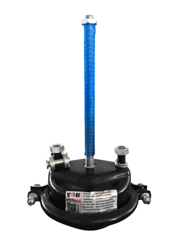 T24 Brake Chamber for Buses and Trailers, FA1007A/B/C VariantsT24 brake chamber for bus and trailer use, with three port and thread variants sharing 64 mm stroke and 285 mm push rod length.View Product →
Air supply parts that keep the circuit dry
Moisture is the quiet killer of air brake systems, so the dryer and its service items deserve their own place on any diagram.
An air dryer sits between the compressor and the first reservoir. Its cartridge, check valve, purge valve and heater show up as separate items, and the silencer or air filter on the exhaust side is often forgotten until the unit starts cycling loudly. If the tanks are wet, replace the cartridge before chasing valve faults that may not exist.
 FA3004A/FA3004B Air Dryer for Military and Off-Road Vehicles24V air dryer with FA3004A/FA3004B and DR31 references, offered for military, off-road and personnel-carrier brake systems with multiple port options.View Product →
Trailer and Coupling Part Names
Trailer parts fall into two groups: what couples the trailer to the tractor, and what carries its braking and electrical signals.
- Fifth wheel (traction seat) — the horseshoe coupling on the tractor; jaws and adjustment shims wear as a set.
- King pin — the pin under the trailer nose; measure diameter and length, not just the label.
- Landing gear — the trailer legs and their internal gearing and crank.
- Air suzie or electric coupler — the coiled electrical lead with plug and socket; pin count and keyway matter.
- Palm coupling and swift joint — colour-coded air connectors, one for supply and one for service.
- Relay emergency valve — protects the trailer circuit if a line breaks or disconnects.
- Trailer brake chamber and slack adjuster — familiar names, different brackets and stroke values.
- Axle nut, U-lock and hub cover — wheel-end hardware usually drawn at the bottom of the trailer view.
Where Diagram Labels Cause Confusion
Almost every wrong-part return traces back to five repeatable mistakes rather than a poor drawing.
- Trusting a single label. Search both names, then confirm the position on the diagram before committing.
- Ignoring the side. Left and right slack adjusters, and some chambers, are mirrored and not interchangeable.
- Skipping the size code. A T24 and a T30 chamber share a silhouette but not a stroke value.
- Ordering a component when the drawing shows a kit. Shoe kits, relay valve kits and dryer kits include hardware the photo never shows.
- Reading position as part number. Diagrams show location; catalogues list numbers. The two have to be cross-checked.
| Diagram label | Also called | What to confirm |
|---|---|---|
| Fender | Wing | Side, wheel-arch liner, mounting hole pattern |
| Hub cover | Hub cap | Bolt circle, depth, oil or grease fill type |
| Fifth wheel | Coupling plate | Jaw size, mounting height, adjustment shims |
| Wheel nut | Tire screw | Thread, cone type, length, torque class |
| Slack adjuster | Brake adjuster | Manual or automatic, spline count, arm length |
| Air suzie | Electrical coil | Pin count, keyway, cable length |
A Practical Ordering Checklist
Order from a five-line description rather than a part name alone, and the return rate drops immediately.
- Name the system and position: "rear axle, left side, service chamber".
- Photograph the old part from three angles, including ports and bracket.
- Record every code on the casting: size, port thread, stroke, spline count.
- State quantity and side, and whether the item is a kit or a single component.
- Confirm the foundation brake type, drum or disc, since chambers do not swap between them.
- Check the catalogue by system rather than by guessed name, then verify dimensions against the drawing.
The full parts catalogue is grouped by system for exactly this reason: finding the right category first is faster than searching a half-remembered label.
Frequently Asked Questions
What are the main parts of a truck shown in a diagram?
Most diagrams cover six groups: cab and body panels, frame and suspension, driveline, air brake system, wheels and tyres, and trailer coupling. A typical service drawing labels between forty and eighty items, so grouping by zone keeps it readable.
Why does the same truck part have different names?
Regional usage is the main reason: fender and wing, hood and bonnet, wheel nut and tire screw all describe identical hardware. The diagram resolves the ambiguity because it shows position, and position is what a supplier needs.
Can a brake chamber be identified from a photo alone?
Not reliably. A photo confirms the general shape, clamp band style and port layout, but stroke, port thread and mounting pattern still have to be read from the casting or measured on the bench.
What is the difference between a brake chamber and a slack adjuster?
The chamber converts air pressure into linear pushrod force; the slack adjuster converts that force into cam rotation and maintains lining clearance. A manual adjuster needs periodic setting, an automatic one compensates as the lining wears.
How do I find a part number without a usable diagram?
Start with the system, then measure. Bore, stroke, thread, spline count and mounting hole spacing will narrow a category to a handful of candidates, and a dimensional check beats a visual match almost every time.

 Contact Us